Journal #Four [DAT601] - Comparing the Conceptual Model with the Relational Model
![Journal #Four [DAT601] - Comparing the Conceptual Model with the Relational Model](/assets/images/j4header.PNG)
Comparing the Conceptual Model with the Relational Model
JOURNAL #FOUR [DAT601]
Learning Summary
GOING FROM CONCEPTUAL TO LOGICAL…[AND BACK AGAIN!]
The Relational Model
Class sessions discussed the move from the Conceptional Model to the Relational (Logical) Model, and the rules and constraints that govern the process.
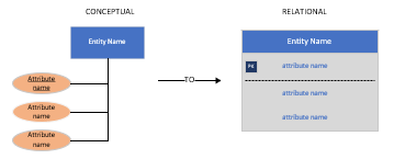
The Relational Model was developed in 1970 by Codd. The main difference between the Conceptual Model and Relational Model is that the Conceptional Model is entity specific, whereas the Relational Model is table specific, this can be viewed in the diagram above.
The tables in the Relational Model have a specific number of columns, but an unlimited number of rows, or Tuples. A set of Tuples is a record. The columns are the attributes and each attribute must have a domain.
WHAT
Making a Comparison
| Conceptual | Relational |
|---|---|
| Represents a group of objects called entities and identifies the relationships between them | Represents a group of tables and defines the relationships between them |
| Data is categorised as Entity set, Relationship and Attribute | Data is categorised as Domain, Attributes and Tuples |
| Easier to understand the relationships | Can be more difficult to define relation between the tables |
| Includes cardinality | Does not include cardinality |
Rules when moving to the Relational Model
ENTITIES
- An entity type becomes a table and generally keeps the same name
- Entities contain an Attribute or Attributes that make up the Primary Key (PK), if there is more then one attribute that makes up the PK this is a Composite Key (CK)
- Weak entities contain the Foreign Key (FK) of their parent entity
ATTRIBUTES
- Attributes become columns within the table
- The key attribute of the entity in the Conceptual Model may likely become the Primary Key (PK) in the Relational Model
- Multi-valued Attributes become tables, the parent entity will then become a Foreign Key (FK) in the table
RELATIONSHIPS
- Relationships with attributes will become tables, this is because in the relational model there are no relationships
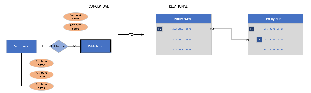
- In one-to-one relationships the PK of one of the entities will become the FK of the other, the decision as to which one is the problem of the designer
- In a one-to-many relationship the ‘many entity’ takes the PK from the ‘one entity’ as a FK
- In order to resolve the many-to-may relationship a join table must be created, this table includes both PKs for the entities it joins together which are represented as FKs, which become the Composite Key (CK) of the table
PARTICIPATION
- As a rule the PK on the mandatory participation side will become the foreign key on the optional participation side
SUPERCLASS/SUBCLASS
- There is not one, singular solution when dealing with Superclass and Subclass. There are three potential solutions to the problem:
| Solution 1 | Solution 2 | Solution 3 |
|---|---|---|
| The superclass becomes a table in the relational diagram that has the attributes that are shared by all subclasses, then each subclass becomes a table containing their unique attributes | Completely remove the superclass from the relational diagram, instead each subclass becomes a table with all common attributes plus their own unique attributes | The superclass becomes a table that holds all common attributes and the unique attributes of each subclass |
Crows Foot
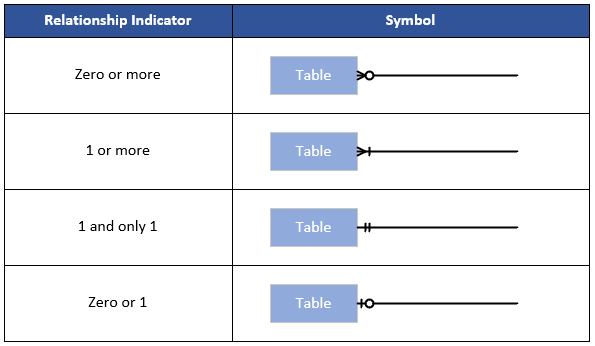
Crows Foot notation is a data modelling technique used within the Relational Modelling Diagram. It was created by Gordon Everest and named after the fork in the cardinality of the many-to-many relationship, like the toes of a crows foot.
In crows foot, cardinality represents the maximum number of instances that a entity is associated with its related entity. This is indicated by 1 or Many. Modality is the opposite and represents the minimum number of occurrences. This is indicated by a 0 or 1.
Crows Foot is represented in the following legend:
WHY
The logical modelling diagram is developed to both improve the system and how it is visualised. The relational model details the events that take place and lists the data required. There is a further benefit in producing the relational diagram in that it builds the foundations for the creation of the Physical diagram.
Logical diagrams can often be used to allow for a better understanding of the database by the non-technical business team. This is extremely beneficial to the development team as it allows them to include the business team in the process, this can be extremely useful as it allows the business team to route out errors made in the assumptions, and identify any shortcomings within the database design.
HOW
The process of going from Conceptual to Relational can in some ways be quite straightforward. A lot of system visualisation has been achieved and therefore it capable of providing a far greater understanding of what the business outcome which is an asset shared amongst the teams involved.
The key is to follow the rules as outlined above and understand where decisions have to be made as to which route to follow. This is especially important with the more abstract elements such as multi-valued attributes, relationships which contain their own attributes and the move from a relationships structure into Primary Keys and Foreign Keys. On a whole however the rule structure is logical to follow.
Milestone 1 - Conceptual Updates
At lot of effort has been put in this week to tighten the Conceptual Model. Changes have, as a result, been made to the documentation including Business Rules and the Data Dictionary and will be included in the report submission and not posted to these blogs.